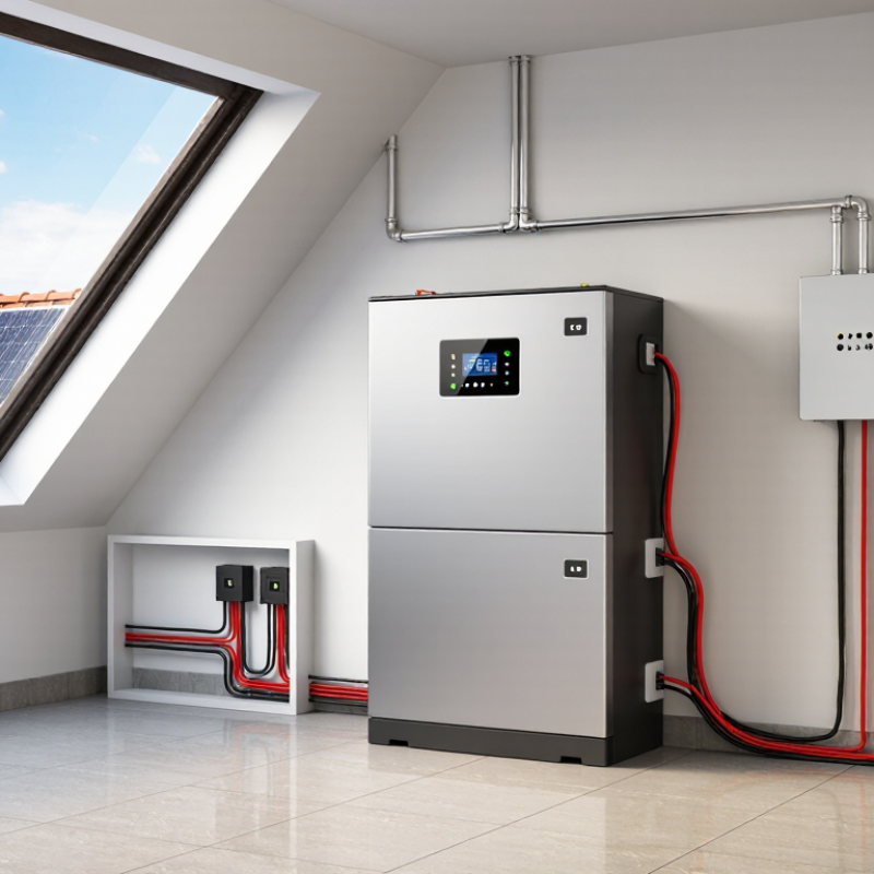
| Battery Chemistry | Common solar-storage chemistries include lithium iron phosphate (LiFePO4) and nickel-manganese-cobalt (NMC). | Choose a controller with adjustable charging voltage and a battery profile that matches the manufacturer’s specifications. | Different lithium chemistries have different voltage limits, temperature requirements, and charging behavior. |
| Nominal Battery Voltage | Typical systems are marketed as 12 V, 24 V, or 48 V. A 12 V LiFePO4 battery commonly contains four series-connected cells and has a nominal voltage of approximately 12.8 V. | Confirm that the controller supports the battery bank’s nominal voltage and automatically detects or allows manual selection of the correct system voltage. | A controller designed for the wrong voltage can cause undercharging, overcharging, or system shutdown. |
| Absorption or Constant-Voltage Setting | For many 12 V LiFePO4 batteries, the manufacturer’s recommended charging voltage is commonly around 14.0–14.6 V. The equivalent range is approximately 28.0–29.2 V for a 24 V bank and 56.0–58.4 V for a 48 V bank. | Use only the voltage range specified by the battery manufacturer. Select a controller with precise voltage adjustment rather than relying on a fixed lead-acid setting. | Lithium batteries have narrow maximum-voltage limits, and excessive voltage can activate the battery management system or damage cells. |
| Float-Charge Behavior | Lithium batteries generally do not require continuous high-voltage float charging after reaching full charge. Some systems use a lower maintenance voltage or disable float charging. | Choose a controller that allows float voltage reduction, float cancellation, or a lithium-specific charging profile. | Maintaining a lithium battery at a high voltage for long periods may increase cell stress and reduce service life. |
| Charge Current | A common design range is approximately 0.2C–0.5C, where C is the battery capacity in amp-hours. For example, a 100 Ah battery may commonly be charged at about 20–50 A, subject to the battery specification. | Ensure the controller’s maximum output current does not exceed the battery’s permitted charge current or the battery management system’s limits. | Excessive current can cause protective shutdowns, overheating, or accelerated battery aging. |
| Solar Array Sizing | Controller output is approximately calculated as battery charging voltage multiplied by charging current. A 12 V system charging at 30 A requires roughly 430–450 W of usable charging power before system losses. | Check the controller’s maximum photovoltaic input power, input current, and open-circuit voltage. Include temperature-related increases in panel open-circuit voltage. | Oversizing the solar array beyond the controller’s limits can create an unsafe or non-compliant installation. |
| MPPT or PWM Technology | MPPT controllers continuously adjust the operating point of the solar array and generally provide better energy harvest, especially when panel voltage is higher than battery voltage or conditions change. | Use an MPPT controller when maximizing energy yield, supporting higher-voltage arrays, or operating in variable sunlight is important. PWM may suit small, closely matched systems. | The controller type affects solar harvest, wiring requirements, array configuration, and overall system efficiency. |
| Low-Temperature Charging | Most lithium batteries should not be charged below 0°C unless specifically designed and approved for low-temperature charging. Some batteries include heating elements or temperature-controlled charging. | Select a controller with a temperature sensor, low-temperature charging cutoff, or a communication link to the battery management system. | Charging lithium cells below the permitted temperature can cause permanent lithium plating and capacity loss. |
| Battery Management System Compatibility | A battery management system typically monitors cell voltage, pack temperature, current, and protection limits. | Make sure the controller can safely respond if the BMS disconnects the battery. For advanced systems, use compatible communication protocols such as CAN or RS-485 when specified. | The BMS is the final protection layer, but repeated unexpected disconnects can affect controller operation and system stability. |
| Temperature Compensation | Lithium charging voltage generally should not be compensated in the same way as lead-acid batteries. Temperature-based voltage increases used for lead-acid charging may be unsuitable for lithium batteries. | Disable lead-acid temperature compensation unless the lithium battery manufacturer explicitly requires it. Use temperature sensing primarily for low-temperature charging protection. | Incorrect compensation can raise charging voltage beyond the battery’s safe operating range. |
| Absorption Duration | Lithium batteries usually require a short absorption period or an end-of-charge condition based on current and voltage. They do not normally need prolonged absorption. | Choose a controller with adjustable absorption time or a lithium profile that terminates or reduces charging after the battery reaches the specified conditions. | Shorter, controlled absorption reduces unnecessary time at high state of charge and can improve battery longevity. |
| Low-Voltage Disconnect and Load Control | Lithium batteries maintain a relatively stable voltage until they are close to empty, then voltage can fall rapidly. | Use battery state-of-charge data from the BMS when available. Do not rely only on voltage-based state-of-charge estimates, especially under changing loads. | Voltage alone is less accurate for estimating remaining capacity in lithium batteries than in many lead-acid systems. |
| Protection and Electrical Safety | Required protection commonly includes correctly rated fuses or circuit breakers, suitable cable sizes, disconnects, and secure terminals. | Verify maximum input and output current ratings, reverse-polarity protection, over-temperature protection, and compliance with applicable electrical codes. | Correct protection limits fault energy, prevents cable overheating, and improves maintenance safety. |
| Monitoring and Data Access | Useful parameters include battery voltage, charge current, solar power, accumulated energy, temperature, alarms, and charging stage. | Prefer a controller with a clear display, remote monitoring, event history, or communication capability when the system is unattended or mission-critical. | Accurate monitoring helps identify shading, wiring losses, abnormal temperatures, and BMS protection events. |
| System Expansion | Future expansion may increase battery capacity, solar array power, or both. | Allow adequate margin in controller current, photovoltaic input voltage, heat dissipation, wiring, and protective-device ratings. | Planning for expansion avoids replacing the controller when additional storage or solar generation is added. |